This Epson SC-P5000 Series, Pro 4900, Pro 4910 printers Service Manual, Exploded View, Parts List and Block Wiring Diagram describes basic functions, theory of electrical and mechanical operations, maintenance and repair procedures of the printer.
 Security policy
Read our Privacy policy
 Payment methods
Debit/Credit cards, BTC/ETH/LTC/USDT
 Return policy
Read our return policy
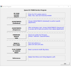
For making printer adjustments and maintenance You can use Epson SC-P5000 Service Program
Chapter 1 PRODUCT DESCRIPTION
1.1 Product Description
1.2 Basic Specifications
1.2.1 Basic Specifications
1.2.2 Electric Specifications
1.2.3 Ink Specifications
1.2.4 General Specifications
1.2.5 Reliability/Durability
1.3 Printing Specifications
1.3.1 Paper Feed Specifications
1.3.2 Paper Specification
1.3.2.1 Supported Paper
1.3.2.2 Designated Paper
1.3.3 Printable Area
1.3.4 Borderless Printing Specification
1.3.5 Cutting of Roll Paper
1.4 Hardware Specifications
1.4.1 Dimensions and Weight
1.4.2 Part Names
1.5 Control Panel
1.5.1 Setup Menu
1.5.1.1 SC-P5000 Series Setup Menu
1.5.1.2 Epson Stylus Pro 4900/4910 Setup Menu
1.5.2 Maintenance Mode
1.5.3 Serviceman Mode
Chapter 2 TROUBLE SHOOTING
2.1 Overview
2.1.1 Preliminary Check
2.1.1.1 Check for the usage environment
2.1.1.2 Recurrence check of the trouble
2.1.1.3 Check for the counter values/history
2.1.1.4 Test print check
2.1.2 Troubleshooting Procedure
2.1.3 Procedure after troubleshooting
2.1.3.1 If the trouble has been successfully solved
2.1.3.2 If necessary to escalate the trouble case
2.2 Remedies for Maintenance Requests
2.3 Remedies for Service Call Error
2.4 Remedies for Error Messages related to SpectroProofer
2.5 Remedies for Print Quality Troubles
2.6 Trouble on Paper Feeding
2.7 Printer does not Operate
2.8 Abnormal Operations
2.9 Problems on SpectroProofer
2.10 Trouble on Service Program
2.11 Trouble on NVRAM Viewer
2.12 Trouble on Colorimetric Calibration Adjustment program
Chapter 3 DISASSEMBLY & ASSEMBLY
3.1 Overview
3.1.1 Precautions
3.1.2 Cautions after assembling
3.1.3 Orientation Definition
3.1.4 Recommended Tools
3.2 Parts Diagram
3.3 Disassembly Flowchart
3.4 Disassembly and Assembly Procedure
3.4.1 Preparation for servicing
3.4.1.1 Unlocking the CR Unit
3.4.1.2 Roll Unit
3.4.1.3 Paper Cassette
3.4.1.4 Cutter Replacement
3.4.1.5 Maintenance box 1
3.4.1.6 Maintenance Box2
3.4.1.7 Ink Cartridge Replacement
3.4.1.8 Spindle
3.4.1.9 Mounter
3.4.2 Housing
3.4.2.1 Printer Cover
3.4.2.2 Upper Front Cover
3.4.2.3 Printer Cover Sensor
3.4.2.4 Control Panel Cover
3.4.2.5 Left Cover
3.4.2.6 Right Upper Cover
3.4.2.7 Right Cover
3.4.2.8 Left IC Cover Frame/Right IC Cover Frame/
Left IC Sensor/Right IC Sensor
3.4.2.9 Front Cover
3.4.2.10 Front Cover Sensor
3.4.2.11 Rear Cover
3.4.2.12 Rear Unit
3.4.2.13 Rear Unit Sensor
3.4.2.14 Board Tray
3.4.2.15 Media Eject Cover
3.4.2.16 CR Cover
3.4.2.17 Mid-Right Cover/Mid-Left Cover
3.4.2.18 Left Roll Cover/Right Roll Cover
3.4.3 Electric Circuit Components
3.4.3.1 Main Board
3.4.3.2 Network Board
3.4.3.3 Power Supply Box
3.4.3.4 Power Supply Board
3.4.3.5 SUB Board
3.4.3.6 SUB-B Board
3.4.3.7 SUB-C Board
3.4.3.8 SUB-D Board
3.4.3.9 AID Board
3.4.3.10 LED Board
3.4.3.11 Control Panel Board
3.4.4 Carriage Mechanism
3.4.4.1 CR Motor
3.4.4.2 CR Encoder
3.4.4.3 CR Scale
3.4.4.4 Ink Mark Sensor
3.4.4.5 CR Unit/CR Belt
3.4.4.6 APG Motor Assy
3.4.4.7 APG Sensor
3.4.4.8 Oil pad holder
3.4.5 Paper Feed Mechanism
3.4.5.1 PF Motor
3.4.5.2 PF Encoder
3.4.5.3 PF Scale
3.4.5.4 PF Belt
3.4.5.5 Suction Fan
3.4.5.6 PE Sensor
3.4.5.7 2nd PE Sensor
3.4.5.8 PW Sensor
3.4.5.9 Paper Thickness Sensor1, 2
3.4.5.10 Release Motor Assy
3.4.5.11 Release Sensor
3.4.5.12 Edge Release Assy
3.4.5.13 Edge Sensor
3.4.6 ASF Unit
3.4.6.1 ASF Motor Assy
3.4.6.2 ASF Sub Motor Assy
3.4.6.3 Pickup Roller
3.4.6.4 Assist Roller Sensor/Retard Roller Sensor/
Pickup Unit Sensor
3.4.6.5 Retard Roller
3.4.6.6 Paper Empty Sensor
3.4.6.7 Paper Cassette Sensor
3.4.7 ROLL Unit
3.4.7.1 Roll Unit Sensor
3.4.7.2 Roll Lock Sensor
3.4.7.3 ATC Motor Assy
3.4.7.4 Roll Feeding Motor Assy
3.4.7.5 Paper Guide Sensor
3.4.7.6 Roll Feeding Sensor
3.4.7.7 Antistatic Cloth Unit
3.4.8 Cutter Unit
3.4.8.1 Cutter Cover
3.4.8.2 Cutter Motor Assy
3.4.8.3 Cutter HP Sensor
3.4.8.4 Cutter Unit
3.4.9 Ink System Mechanism
3.4.9.1 Ink Selector Assy
3.4.9.2 Printhead
3.4.9.3 IS Unit
3.4.9.4 Wiper
3.4.9.5 Wiper Cleaner
3.4.9.6 Head Cap
3.4.9.7 Home (Right) Side Cartridge Holder
3.4.9.8 Full (Left) Side Cartridge Holder
3.4.9.9 Maintenance box 1 Holder
3.4.9.10 Ink Tubes
3.4.9.11 Head FFC
3.4.9.12 Right Holder FFC
3.4.9.13 Left Holder FFC
3.4.9.14 Decompression Pump
3.4.10 Color Measurement Device and Backing Replacement
3.4.10.1 Color Measurement Device
3.4.10.2 Backing/White calibration tile holder
3.4.11 Housing
3.4.11.1 Upper Cover
3.4.11.2 I/F Cover
3.4.11.3 Right Cover
3.4.11.4 Left Cover
3.4.11.5 Front Cover
3.4.11.6 Magnet Latch
3.4.12 Color Measurement Device Parts
3.4.12.1 Main-C Board
3.4.12.2 Encoder for paper pressing motor
3.4.12.3 Thermistor
3.4.12.4 Drying Fan
3.4.12.5 Paper Pressing Motor
3.4.12.6 CR HP Sensor
3.4.12.7 Backing Sensor
3.4.12.8 CR Motor
3.4.12.9 EJ Planet Lever
Chapter 4 ADJUSTMENT
4.1 Overview
4.1.1 Precautions
4.1.2 Adjustment Items and the Order by Repaired Part
4.1.3 Description of Adjustments
4.1.4 Tools/Consumables for Adjustments
4.1.5 Service Program Basic Operations
4.2 NV-RAM BACKUP UTILITY/NVRAM Viewer
4.2.1 NVRAM Read Procedure
4.2.2 NVRAM Write Procedure
4.2.3 NVRAM Viewer Basic Operation
4.3 ADJUSTMENTS (Individual)
4.4 ADJUSTMENTS (Sequence)
4.5 Installing Firmware
4.6 Image & Test Print
4.7 Counter Reset
4.8 References
4.9 Initial Ink Charge Flag
4.10 CR Related Check & Adjustments
4.10.1 FFC Position Check
4.10.1.1 FFC Position Check after replacing the Head FFC
4.10.1.2 FFC Position Check after replacing the tube
4.10.2 CR Belt Adjustment
4.10.3 PG Height Check & Adjustment
4.10.4 APG Check
4.10.5 CR Encoder and Scale Check
4.10.6 CR Speed Initialize
4.10.7 Active Damper Adjustment
4.10.8 Ink Mark Sensor Check & Adjustment
4.11 Head Related Checks and Adjustments
4.11.1 Head ID Check & Input
4.11.2 Nozzle Check
4.11.3 Cleaning
4.11.4 CR & PF Direction Head Slant Adjustment
4.11.4.1 CR Direction Head Slant Adjustment
4.11.4.2 PF Direction Head Slant Adjustment
4.11.5 Auto Bi-D Adjustment
4.11.6 Colorimetric Calibration (Color ID)
4.11.6.1 Adjustment Overview
4.11.6.2 Adjusting Method
4.12 Ink Supply Related Checks and Adjustments
4.12.1 Wiper and Cap Cleaning & Exchange
4.12.2 Maintenance Box Remaining Space Check
4.12.3 Ink Eject and Initial Charge
4.12.3.1 Ink Eject
4.12.3.2 Ink Charge
4.12.4 Ink Selector Movement Check
4.12.5 ILS & CSIC Check
4.12.5.1 ILS Check
4.12.5.2 CSIC Check
4.12.6 Tubes Cleaning (and Ink Charge per Two Rows)
4.12.6.1 Tubes Cleaning
4.12.6.2 Ink Charge
4.12.7 Leak Check (visually)
4.12.8 LLK/V Ink Change (SC-P5000 Series)
4.13 Media Feed Related Checks and Adjustments
4.13.1 PF Belt Adjustment
4.13.2 PF Encoder and Scale Check
4.13.3 Paper Thickness Sensor Position Adjustment
4.13.4 Rear AD Adjustment
4.13.5 Media Feed Correction Check & Adjustment
4.13.6 Media Eject Correction Check & Adjustment
4.13.7 PW + T&B&S Check & Adjustment
4.13.7.1 PW Adjustment
4.13.7.2 T&B&S Adjustment
4.13.8 Cut Position Check & Adjustment
4.13.9 Cutter Belt Tension Check
4.13.10 Suction Check & Adjustment
4.14 Boards Related Checks and Adjustments
4.14.1 RTC&USB ID
4.14.2 Serial Number Check & Input
4.14.3 AID Function Check
4.14.4 MAC Address Check & Input
4.14.5 USB Port and Network Communication Check
4.14.6 Default Reset
4.14.7 Operation Panel Check (Buttons & LCD)
4.14.7.1 Button Operation Check
4.14.8 Color Mode Settings (SC-P5000 Series)
4.15 Other Printer Checks and Adjustments
4.15.1 Motor Measurement Adjustment
4.15.2 Sensor Check
4.15.3 Encoder Check
4.16 SpectroProofer Related Adjustments
4.16.1 SpectroProofer Sensor Check
4.16.1.1 Backing Sensor Check
4.16.1.2 Thermistor Check
4.16.2 SpectroProofer Movement Check
4.16.2.1 Fan Function Check
4.16.2.2 CR Function Check
4.16.2.3 Paper Press Function Check
4.16.3 SpectroProofer Measurement Precision Check
(Epson Stylus Pro 4900/4910 only)
4.16.4 SpectroProofer Serial Number Check & Input
4.17 SpectroProofer Checker (SC-P5000 Series)
4.17.1 Inspection Outline
4.17.2 Inspection Procedure
Chapter 5 MAINTENANCE
5.1 Overview
5.2 Setting Up/Storing the Printer
5.2.1 Setting Up
5.2.2 Storing the Printer and Cleaning the Ink Path
5.3 Transportation
5.4 Cleaning
5.4.1 Main Unit
5.4.2 Auto Color Measurement Device Mounter
5.5 Lubrication
Chapter 6 APPENDIX
6.1 Block Wiring Diagram
6.1.1 Main Body
6.1.2 SpectroProofer
6.2 Connection Diagram
6.2.1 Housing
6.2.2 Electric Circuit Components 1
6.2.3 Electric Circuit Components 2
6.2.4 Carriage Mechanism
6.2.5 Paper Feed Mechanism 1
6.2.6 Paper Feed Mechanism 2
6.2.7 ASF Unit
6.2.8 ROLL Unit
6.2.9 Cutter Unit
6.2.10 Ink System Mechanism 1
6.2.11 Ink System Mechanism 2
6.2.12 SpectroProofer
6.3 Panel Menu Map
6.4 Part names used in this manual
6.5 Exploded Diagram/Parts List
Data sheet
This Epson SC-P5000 Series, Pro 4900, Pro 4910 printers Service Manual, Exploded View, Parts List and Block Wiring Diagram describes basic functions, theory of electrical and mechanical operations, maintenance and repair procedures of the printer.