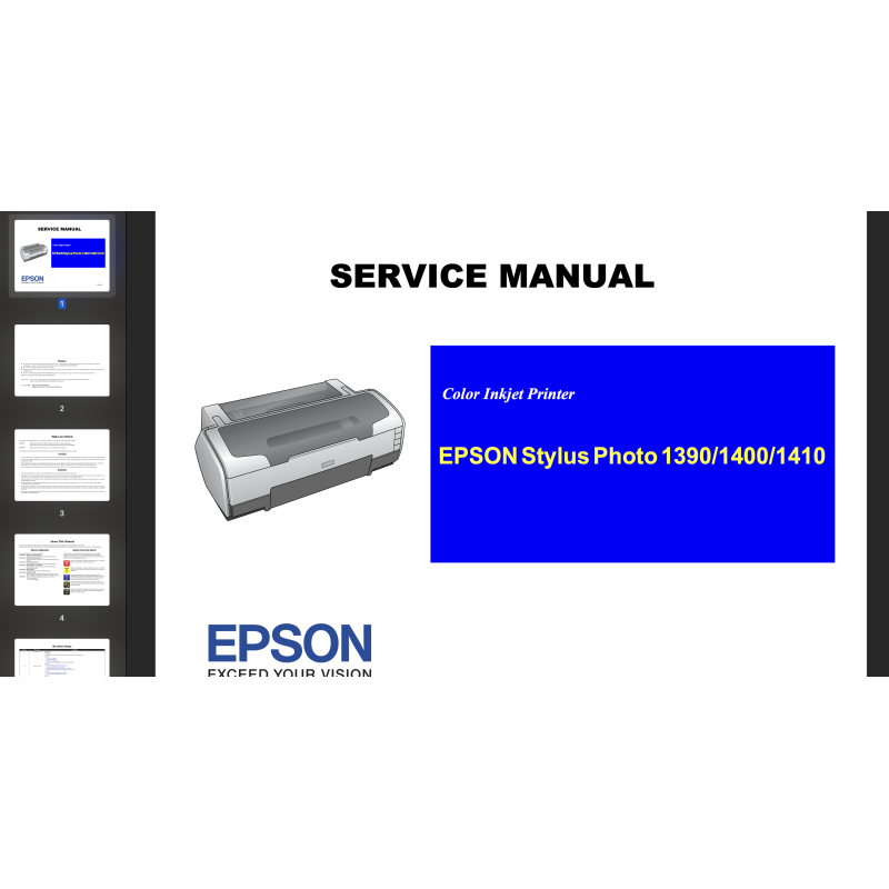


Epson R1390, R1400, R1410 printers Service Manual and Parts List describes basic functions, theory of electrical and mechanical operations, maintenance and repair procedures of the printer.
 Security policy
Read our Privacy policy
 Payment methods
Debit/Credit cards, BTC/ETH/LTC/USDT
 Return policy
Read our return policy
For making printer adjustments and maintenance You can use Epson Photo 1390 Service Adjustment Program
Chapter 1 PRODUCT DESCRIPTION
1.1 Overview
1.2 Printing Area
1.2.1 Printing Area (Cut sheet, Envelope)
1.3 PG Setting
1.4 Printer Function
1.4.1 Operator Controls
1.4.2 Buttons
1.4.3 LED Indicators
1.4.4 Panel Functions
1.4.5 Printer Condition and Panel LED Status
1.4.6 Errors
1.5 Size and Weight
1.6 Accessories
Chapter 2 OPERATING PRINCIPLES
2.1 Overview
2.2 Printer Mechanism
2.2.1 Carriage Mechanism
2.2.2 Printhead Specifications
2.2.3 Paper Feeding Mechanism
2.2.4 Paper Feeding Mechanism
2.2.5 Ink System Mechanism
2.2.6 Ink Sequence
2.2.7 Power-On Sequence
2.3 Electrical Circuit Operating Principles
2.3.1 Power Supply Circuit Operating Principle
2.3.2 C655 MAIN Circuit Operating Principle
Chapter 3 TROUBLESHOOTING
3.1 Overview
3.1.1 Troubleshooting according to Panel Messages
3.1.2 Troubleshooting based on Observed Faults
Chapter 4 DISASSEMBLY AND ASSEMBLY
4.1 Overview
4.1.1 Precautions
4.1.2 Tools
4.1.3 Screws
4.1.4 Work Completion Checklist
4.1.5 Sharp Metal Edges
4.1.6 Method for making CSIC board removal tool
4.2 Disassembly/Assembly Procedures
4.2.1 Removing the Housings
4.2.2 Waste Ink Pad
4.2.3 Front Paper Guide Pad
4.2.4 ASF Assy
4.2.5 Removing the Boards
4.2.6 Disassembling the Printer Mechanism
4.2.7 Removing the Motors
4.2.8 Removing the Sensors
4.3 Procedure Specific to Stylus Photo 1390
4.3.1 Upper Housing
4.3.2 Paper EJ Frame Assy
Chapter 5 ADJUSTMENT
5.1 Adjustment Items and Overview
5.1.1 Servicing Adjustment Item List
5.1.2 Replacement Part-Based Adjustment Priorities
5.1.3 Required Adjustment Tools
5.2 Adjustment
5.2.1 PF Belt Tension Adjustment
5.2.2 PG Adjustment
5.2.3 PF Roller Shaft Center Support Position Adjustment
Chapter 6 MAINTENANCE
6.1 Overview
6.1.1 ROM Replacement
6.1.2 Cleaning
6.1.3 Service Maintenance
6.1.4 Lubrication
Chapter 7 APPENDIX
7.1 Connector Summary
7.1.1 Connectors and Pin Layouts
7.2 Exploded Diagrams and Parts List
7.3 Electrical Circuit Diagrams
Data sheet