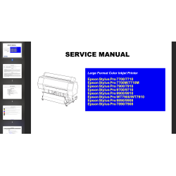
This Epson Pro 7400, 7450, 7800, 7880, 7880C, 9400, 9450, 9800, 9880, 9880C , PX9500, PX9500S, PX7500N, PX7550, PX7550S, PX9500, PX9500S, PX7500, PX7500S Service Manual and Parts List describes functions, theory of electrical and mechanical operations, maintenance and repair procedures of the printer.
 Security policy
Read our Privacy policy
 Payment methods
Debit/Credit cards, BTC/ETH/LTC/USDT
 Return policy
Read our return policy
Chapter 1 Product Description
1.1 Product Description
1.1.1 Features
1.1.2 Difference between 8 color and 4 color machines
1.2 Basic Specifications
1.2.1 Print Specifications
1.2.2 Character Specifications
1.2.3 Operability Specifications
1.2.4 Paper Specifications
1.2.5 Mechanism Specifications
1.2.6 Electrical Related Information
1.2.7 Reliability
1.2.8 Environmental Conditions
1.2.9 Overall Dimensions
1.2.10 Accessories/Options/Consumables
1.3 External View and Parts Names
1.4 Control Panel
1.4.1 Buttons and Functions
1.4.2 Panel Display
1.4.3 Job Information
1.4.4 Panel Setting
1.4.5 Maintenance Mode
1.4.6 SERVICEMAN MODE
1.4.7 MIB Function
1.4.8 Function to Prevent Irregular Printing
1.4.9 Initialization
1.4.10 Default Setup Values
1.5 Controller
1.6 Interface
1.6.1 USB interface
1.6.2 IEEE1394 Interface
1.6.3 Optional Interface
1.6.4 Network Interface
1.6.5 Received Buffer Full Operation
1.6.6 Interface Selection
1.7 Optional Units and Consumables
1.7.1 Ink Cartridge
1.7.2 Cleaning Cartridge
1.7.3 Conversion Cartridge
1.7.4 Maintenance Tank
Chapter 2 Operating Principles
2.1 Overview
2.2 Print Mechanism Components
2.2.1 Print Mechanism (Print Head)
2.2.2 Carriage (CR) Mechanism
2.2.3 Paper Feed Assembly
2.2.4 Cleaning Mechanism
2.2.5 Ink Supply Mechanism
2.2.6 Others
2.3 Outline of Main Board
2.4 Outline of Power Supply Circuit Board
2.5 Colorimetric Calibration (Color ID) Overview
Chapter 3 Troubleshooting
3.1 Overview
3.1.1 Preliminary Check
3.1.2 Troubleshooting Procedure
3.2 Troubleshooting based on Panel Messages
3.2.1 List of Panel Messages
3.2.2 Remedies for Warning Messages
3.2.3 Remedies for Error Messages
3.2.4 Remedies for Service Call Errors
3.3 Troubleshooting based on Printed Result
Chapter 4 Disassembly & Assembly
4.1 Overview
4.1.1 Precautions
4.1.2 Recommended Tools
4.1.3 Recommended Screws
4.2 Disassembly Procedure
4.2.1 Basic Operations
4.2.2 Consumables
4.2.3 Removing the Panel Unit and Housing
4.2.4 Removing the Circuit Boards
4.2.5 Removing the Carriage Mechanism
4.2.6 Removing the Paper Feed Mechanism
4.2.7 Removing the Ink System Mechanism
Chapter 5 Adjustment
5.1 Overview
5.1.1 Precautions
5.1.2 Adjustment Workflow
5.1.3 Parts and Units that Require Adjustments
5.1.4 Required Adjustments by Part or Unit
5.1.5 Description of Adjustments
5.1.6 Tools for Adjustments
5.1.7 Adjustment Program Basic Operations
5.2 Mechanical Adjustment
5.2.1 Ink Mark Sensor Height Adjustment
5.2.2 Cutter Position/Height Adjustment
5.2.3 Paper Thickness Sensor Position Adjustment
5.2.4 CR Timing Belt Tension Adjustment
5.2.5 PF Timing Belt Tension Adjustment
5.2.6 CR Encoder Sensor Adjustment
5.2.7 PF Encoder Sensor Adjustment
5.2.8 Air Leak Check
5.2.9 PG Adjustment
5.3 Basic Adjustment
5.3.1 RTC&USB ID&IEEE1394 ID
5.3.2 Head Rank ID
5.3.3 Input Serial Number
5.3.4 T&B&S (Roll Paper)
5.3.5 T&B&S + 980mm Band Feed
5.3.6 Cutter Pressure Adjustment
5.3.7 Nozzle Bi-D Adjustment
5.3.8 Print Head Slant Adjustment (PF)
5.3.9 Print Head Slant Adjustment (CR)
5.3.10 Ink Mark Sensor Level Adjustment
5.3.11 Auto Uni-D Adjustment
5.3.12 Auto Bi-D Adjustment (P.G. 0.8/1.6)
5.3.13 Ink Mark Sensor Adjustment for Auto Nozzle Check
5.3.14 Skew Check
5.3.15 Platen Position Adjustment
5.3.16 980mm Band Feed Adjustment
5.3.17 Initial Ink Charge Flag ON/OFF
5.3.18 NVRAM Back Up and Write
5.3.19 Initial Ink Charge
5.3.20 Cleaning
5.3.21 Rear Sensor Adjustment
5.3.22 Colorimetric Calibration (Color ID)
5.4 Advanced Adjustment
5.4.1 Auto Bi-D Adjustment
5.4.2 Manual Bi-D Adjustment
5.4.3 Destination Setting
5.4.4 PF Micro Feed Adjustment (Bi-D)
5.5 Check Results
5.5.1 Check Nozzle
5.5.2 Check Alignment
5.5.3 Print Adjustment Check Pattern
5.5.4 Check Cutting
5.5.5 Print Image
5.6 Reset Counters
5.6.1 Reset PG Switching Counter
5.6.2 Reset PF Motor Counter
5.6.3 Reset When CR Unit Change
5.6.4 Reset When Cleaning Unit Change
5.6.5 Reset When PrintHead Change
5.6.6 Reset When Cutter Solenoid Change
5.6.7 Reset Pump Counter
5.6.8 Reset Ink Information
5.7 Installing Firmware
5.8 Model Setting (when replacing the Main Board)
5.9 Writing MAC Address
Chapter 6 Maintenance
6.1 Overview
6.1.1 Product Life Information
6.1.2 Required Maintenance Items
6.2 Lubrication
Chapter 7 Appendix
7.1 Connectors
7.2 Exploded Diagrams
7.3 ASP List (Parts List)
7.3.1 ASP List for Stylus Pro 7400/7800
7.3.2 ASP List for Stylus Pro 9400/9800
7.3.3 ASP List for Stylus Pro 7450/7880/7880C
7.3.4 ASP List for Stylus Pro 9450/9880/9880C
Data sheet
This Epson Pro 7400, 7450, 7800, 7880, 7880C, 9400, 9450, 9800, 9880, 9880C , PX9500, PX9500S, PX7500N, PX7550, PX7550S, PX9500, PX9500S, PX7500, PX7500S Service Manual and Parts List describes functions, theory of electrical and mechanical operations, maintenance and repair procedures of the printer.