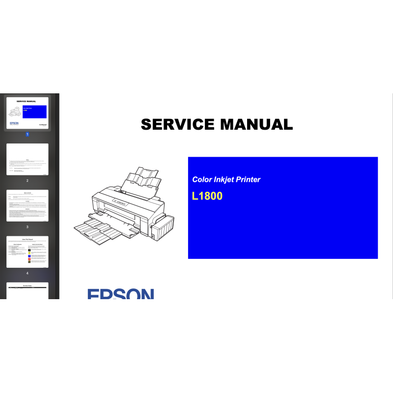


Epson L1800 printers Service Manual describes basic functions, theory of electrical and mechanical operations, maintenance and repair procedures of the printer.
 Security policy
Read our Privacy policy
 Payment methods
Debit/Credit cards, BTC/ETH/LTC/USDT
 Return policy
Read our return policy
For making printer adjustments and maintenance You can use Epson L1800 Service Adjustment Program
Chapter 1 Product Description
1.1 Operation Buttons & Indicators (LEDs)
1.1.1 Operation Buttons
1.1.2 Indicators (LEDs)
1.1.3 Operation Buttons & LEDs Functions
1.1.4 Errors & Remedies
Chapter 2 Troubleshooting
2.1 Overview
2.1.1 Troubleshooting according to Error Messages
2.1.2 Troubleshooting based on Observed Faults
Chapter 3 Disassembly And Assembly
3.1 Overview
3.1.1 Precautions
3.1.2 Tools
3.1.3 Screws
3.1.4 Checks and Precautions before Disassembling
3.1.4.1 Factors which Affect the Print Quality
3.1.4.2 Factors which Affect the Safety of Service Personnel such as Ink Leakage during Operation
3.1.5 Protection for Transportation
3.1.6 Locking/Releasing the Carriage
3.1.7 Method for making Adapter Guide Holder removal tool
3.1.8 Disassembly
3.2 Removing the Housings
3.2.1 Paper Support Assy
3.2.2 Stacker Assy
3.2.3 Front Decoration Plate Left/Right
3.2.4 Rear Housing
3.2.5 Panel Unit
3.2.6 Decoration Plate Left/Right
3.2.7 Upper Housing / Printer Cover
3.2.8 Upper Housing Support Assy
3.3 Removing the Boards
3.3.1 Board Assy (Main Board/Power Supply Board)
3.4 Disassembling the Printer Mechanism
3.4.1 APG Assy
3.4.2 CR Scale
3.4.3 Printhead / Adapter Guide Holder
3.4.4 Lower Housing / Printer Mechanism
3.4.5 Carriage Shaft / Carriage Unit
3.4.6 ASF Assy
3.4.7 LD Roller
3.4.8 Retard Roller Assy
3.4.9 Front Paper Guide Pad
3.4.10 Waste Ink Pad
3.4.11 Foot
3.4.12 Paper EJ Frame Assy
3.4.13 Ink System Unit
3.4.14 Front Paper Guide / Paper EJ Roller
3.4.15 PF Roller Shaft
3.4.16 Release Holder Assy
3.4.17 Upper Paper Guide Assys
3.5 Removing the Motors
3.5.1 CR Motor
3.5.2 PF Motor
3.5.3 ASF Motor
3.6 Removing the Sensors
3.6.1 CR Encoder
3.6.2 PF Encoder
3.6.3 PW Sensor
3.6.4 PE Sensor Holder
3.7 Disassembling the CISS section
3.7.1 Adapter section
3.7.1.1 Adapter Cover
3.7.1.2 Adapter
3.7.2 Ink Supply Tube Assy section
3.7.2.1 Tube Guide Sheet/Tube Guide Sheet Sub
3.7.2.2 Tube Guide Sheet (w/Tube Guide Sheet sub)
3.7.2.3 Ink Supply Tube Assy
3.7.3 Ink Supply Tank Tube Assy section
3.7.3.1 Ink Supply Tank Tube Assy
3.7.3.2 Joint
3.7.4 Ink Supply Tank Assy section
3.7.4.1 Valve Position Label
3.7.4.2 Top Cover
3.7.4.3 Tube Valve Holder Front/Rear
3.7.4.4 Valve Lever
3.7.4.5 Ink Supply Tank Assy
3.7.4.6 Bottom Cover/Left Cover/Right Cover/Cover Joint
Chapter 4 Adjustment
4.1 Adjustment Items and Overview
4.1.1 Servicing Adjustment Item List
4.1.2 Required Adjustments
4.1.3 Required Adjustment Tools
4.2 Adjustment Using Adjustment Program
4.2.1 Head angular adjustment
4.2.2 PW Adjustment/First Dot Position Adjustment
4.2.3 Bi-D adjustment
4.2.4 BAND printing adjustment
4.2.5 PF adjustment
4.2.6 PF band adjustment
4.3 Adjustment without Using Adjustment Program
4.3.1 PF Belt Tension Adjustment
4.3.1.1 PF Belt Tension Adjustment Method
4.3.2 PG Adjustment
4.3.2.1 PG Adjustment Method
4.3.3 PF Roller Shaft Center Support Position Adjustment
4.3.4 How to Adjust the PF Roller Shaft Center Support Position
4.3.5 ASF Guide Roller LDs Position Adjustment
4.3.5.1 Adjusting the Position of the ASF Guide Roller LDs
Chapter 5 Maintenance
5.1 Overview
5.1.1 Cleaning
5.1.2 Service Maintenance
5.1.2.1 Head Cleaning
5.1.2.2 Maintenance Request
5.1.3 Lubrication
5.1.3.1 Lubrication of Carriage Shaft
Chapter 6 Appendix
6.1 Connector Summary
Data sheet